MASTR III P25 DSP Exploration
My bench exploration of the M/A-COM MASTR III P25 DSP 9.6 kb/s data path, including Harris SitePro P25IP research, ESP32 interface firmware, captured-stream transmit replay, RSSI telemetry, and early networked receiver-selection work.
- VHF
- P25 Phase 1
- DSP
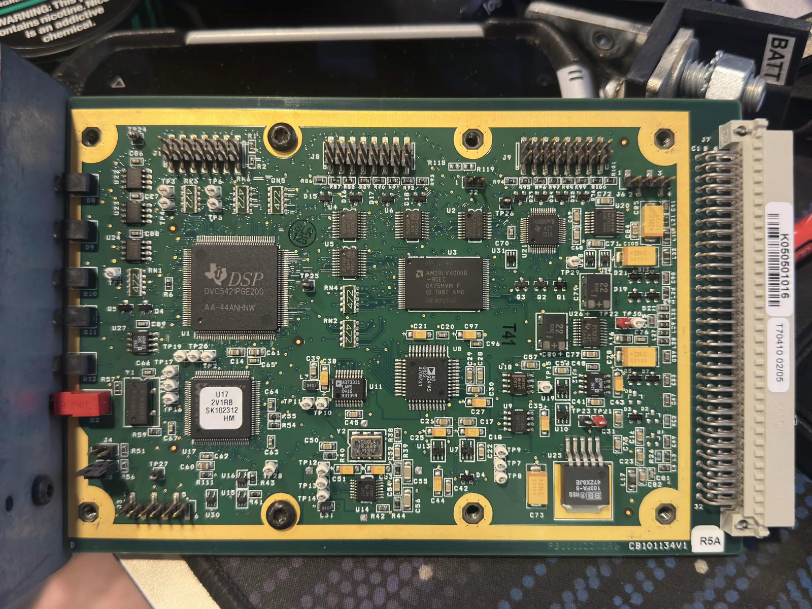
This project tracks my bench exploration of the M/A-COM MASTR III P25 DSP controller and the station’s 9.6 kb/s digital data path. The work started as a way to observe DSP-side P25 receive data, but it has grown into a practical ESP32 interface, transmit-replay test bed, and early networked receiver-selection system.
My long-term goal is to determine whether multiple MASTR III receiver sites can feed logical P25 stream data to a central voter, allowing the system to select the best inbound P25 stream and send it back to transmit-capable sites without relying on analog audio voting.
Proven DSP Interface
So far, I have confirmed that the DSP can be driven into P25 transmit through the external 9.6 kb/s data path when the original captured stream timing and framing are preserved.
The known-good transmit case replays a captured bitstream into 9.6K-TX-DATA-IN on the MASTR III DSP interface. In that setup, I have the ESP32 advance transmit data on the falling edge of the DSP clock, use inverted electrical polarity, assert external PTT, and assert the local TX gate.
The important discovery is that arbitrary synthetic P25 frames were not enough to wake the DSP transmit state machine. The captured stream contains a long lead-in before the first P25 frame sync, and preserving that lead-in appears to be part of the station’s expected call-start behavior.
DSP Interface Schematic
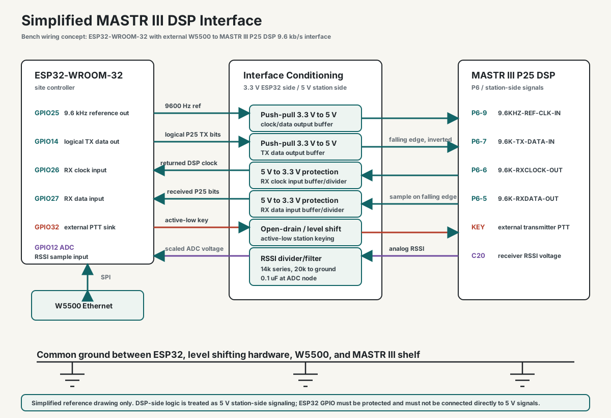
This is the simplified electrical interface I am using for the ESP32-WROOM-32/W5500 site node. It shows the DSP clock/data path, active-low keying, common ground, and RSSI divider/filter arrangement at a block-schematic level.
SitePro P25IP Reference Gap
Part of this work is my attempt to understand how the Harris SitePro controller implemented its P25IP solution specifically for MASTR III stations. Multi-site P25 networking is not unique to SitePro, and commercial solutions exist for many other repeater platforms. As far as I am aware, however, SitePro is the only commercial multi-site P25 solution that was implemented for the MASTR III.
The major limitation is that I do not have a SitePro controller available on the bench for comparison testing. That means I have to infer the behavior from manuals, schematics, DSP firmware artifacts, captured 9.6 kb/s streams, and direct bench measurements rather than observing a working SitePro installation.
Networked Voter Prototype
The current software stack includes ESP32 site-node firmware and a Python central voter. The voter receives packed logical P25 bitstream packets over UDP, scores candidate receiver streams, applies selection hysteresis, and forwards the selected stream back to transmit-capable sites.
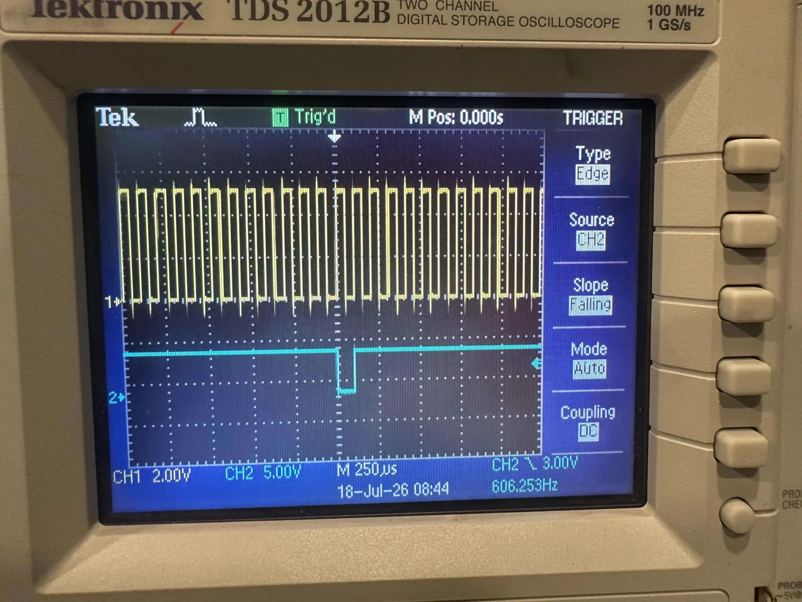
I have tested the ESP32/W5500 firmware as an RX/TX site node with separate DSP timing and network tasks. Bench captures showed the voter-to-ESP32 path is fast enough for current testing, with sub-millisecond RX-to-TX packet timing in the observed runs. I corrected the receiver-side sampling edge to falling-edge sampling after scope captures showed RX data transitions near the rising clock edge.
The dashboard side includes a React interface and Python API for site state, voter controls, routing policy, selection history, call metadata, and RSSI display. P25 metadata decoding currently includes frame sync, NAC, DUID, and LDU1 link-control fields when the captured stream is clean enough to decode.
RSSI Telemetry
I added RSSI telemetry through the site status path. The current bench setup uses a resistor divider into ESP32 ADC, sampled slowly and reported as raw ADC counts and millivolts. The central voter handles voltage-divider scaling and leaves dBm conversion unpopulated until calibration points are collected from known RF levels.
I started testing this implimentation at a faster sample rate, but it correlated with W5500 link drops during RF activity. A follow-up test with the RSSI wire still connected but ADC sampling disabled showed stable networking, pointing at the ADC sampling path rather than the wire alone. However a 1 second sample interval appears usable on the bench, but it remains to be tested further. Idealy I would like the RSSI value to be forwarded allong with every encapsulated P25 datastream packet.
Current Status
The project is active and bench-proven at the interface level. I have confirmed DSP transmit replay using the captured 9.6 kb/s stream, ESP32 clocked GPIO I/O, RX falling-edge sampling, UDP packet transport through a central voter, dashboard/API support, P25 metadata extraction, and RSSI status reporting.
Moving the prototype out to the repeater sites will require significantly more RF hardening. On the bench, a 2 W VHF transmitter operating within about 18 inches of the prototype is enough to cause the Ethernet link to drop. That is especially important because the first candidate deployment site is a very harsh RF environment, with four 50+ kW FM broadcast stations located within roughly 100 feet of the site. Before deploying there, I will need to improve shielding, grounding, power and signal filtering, and cable treatment, then verify that the complete site node remains stable under strong nearby RF. This will all likely be implimented on a custom PCB. When I get to that point, I will cover it in a different write up.
The remaining work is to move from replaying a captured known-good call toward controlled multi RX testing and multi-site voting. My next practical tests are to mutate small regions of the working captured stream, compare multiple captures to identify the minimum required call-start structure, continue mapping likely SitePro/P25IP behavior without a live SitePro reference unit, calibrate RSSI against known RF levels, and continue real-radio call testing through the networked path.